
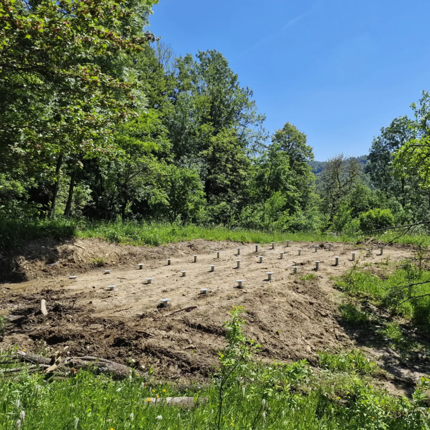
“How many screws do I need?” is one of the most frequent questions we receive.
The short answer is that there is no universal number of foundation screws for 20, 50 or 100 m². A small building may need 4–6 points, while a terrace, a converted container or a modular house can reach 9, 15, 24, 40 or even more.
The difference does not come only from the weight of the building. What matters is where the beams and load-bearing walls are, what distances can exist between supports, what load reaches each point, what the ground is like and what type of screw can be installed to the required depth.
The number of foundation screws is not set by a fixed rule per square metre.
First we understand how the loads are transmitted to the foundation, and we determine the support lines, beams, load-bearing walls, columns and the important points of the structure. Only then are the screws positioned and the model, diameter and length chosen.
Why is there no “one screw per X square metres”?
Because the foundation does not support square metres. The foundation supports the structure.
Suppose we have two buildings of 60 m². The first is a modular building with two rigid longitudinal beams, so the loads can be transmitted through two main support lines. The second also has 60 m², but is made of several modules, has load-bearing interior walls and several structural joints. Three or four support lines may be needed.
Where do we start when determining the number of screws?
The basic question is: through which element does the weight of the building reach each screw?
A foundation screw must sit under a structural element that can transmit the load: a beam, a longitudinal member, a frame, a column, a load-bearing wall, a base plate or a steel distribution structure.
A steel pile installed somewhere under the building does not automatically become useful just because it is under the building's footprint. If there is no element above it capable of transmitting the load, the point is positioned wrongly.
In a modular house, the position of the screws must be correlated with the beams and the joints between modules. In a container, the intermediate points must be placed under longitudinal members, cross-members or distribution beams, not directly under the floor sheet. On a terrace, the distance between supports must allow the beams to work without excessive deflection or vibration.
How many screws are needed, indicatively?
For a first discussion we can use a few indicative ranges. They are not execution configurations and they do not replace design.
| Building type | Indicative number of points |
|---|---|
| Small pergola 3 × 3 / 3 × 4 m | 4–6 |
| Gazebo or carport 4 × 6 m | 6–12 |
| Terrace / deck 20–30 m² | 9–16 |
| 20 ft shipping container | 4–8 |
| 40 ft shipping container | 6–10 |
| Prefabricated module 6 × 3 m | 6–12 |
| Living module 8 × 3 m | 9–15 |
| Modular house 50–80 m² | 15–30 |
| Modular house 80–120 m² | 20–40+ |
| Professional steel structure | by calculation |
These ranges are useful for the order of magnitude. A building can fall outside them if it has heavy loads, significant spans, several storeys, difficult ground, level differences or significant lateral loads.
How many screws are needed for a container?
Here the idea comes up very often: “A container has four corners, so four screws are enough.” Sometimes that may be true, but it is not a rule for all containers.
The original shipping container is designed for handling and stacking through its corner fittings. The situation can change when the container is converted into a dwelling or office and large cut-outs, windows and doors appear, several containers are joined, or interior walls, services, finishes, terraces or other loads are added.
| Container / module | Preliminary range |
|---|---|
| Unaltered 20 ft container, simple use | 4–6 points |
| Converted 20 ft container | 6–8 points |
| 40 ft container | 6–10 points |
| 6 × 3 m module | 6–9 points |
| 8 × 3 m module | 9–15 points |
| Two modules side by side | 12–18 points |
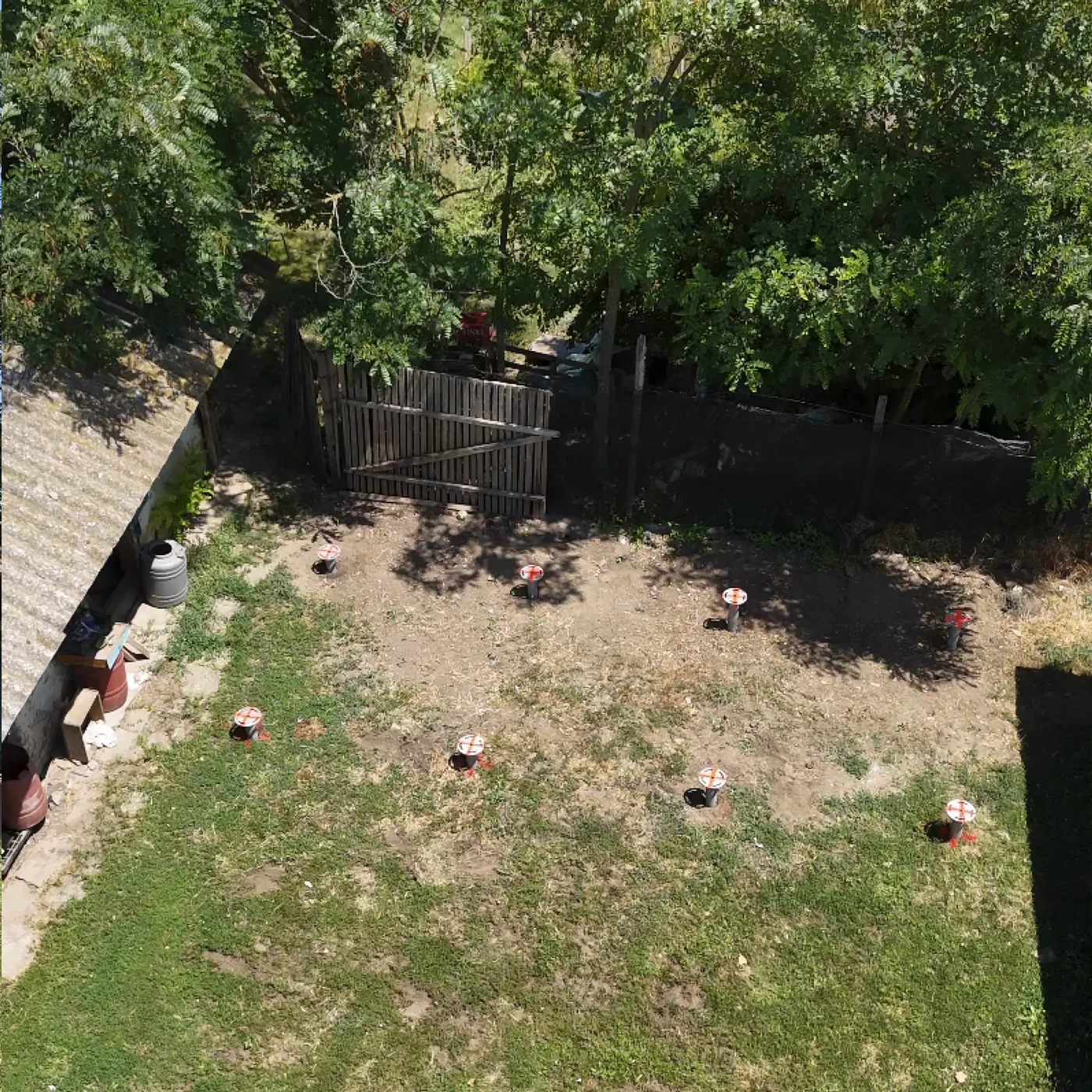
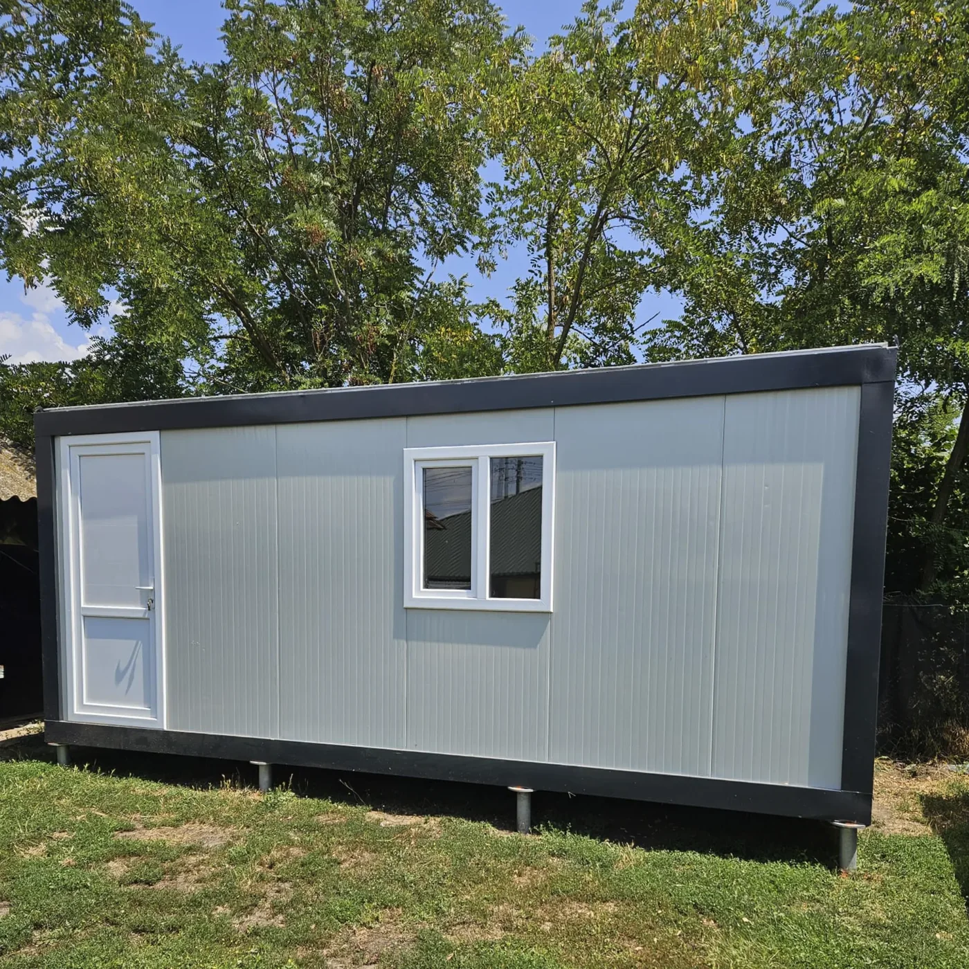
Container of about 8 × 3 m in Giurgiu
The number resulted from the configuration and supports of that particular building. There is no rule “15 points for 8 × 3 m”. Another container with the same dimensions can have 9, 12, 15 or another number of points, depending on the chassis, the structure and the site.
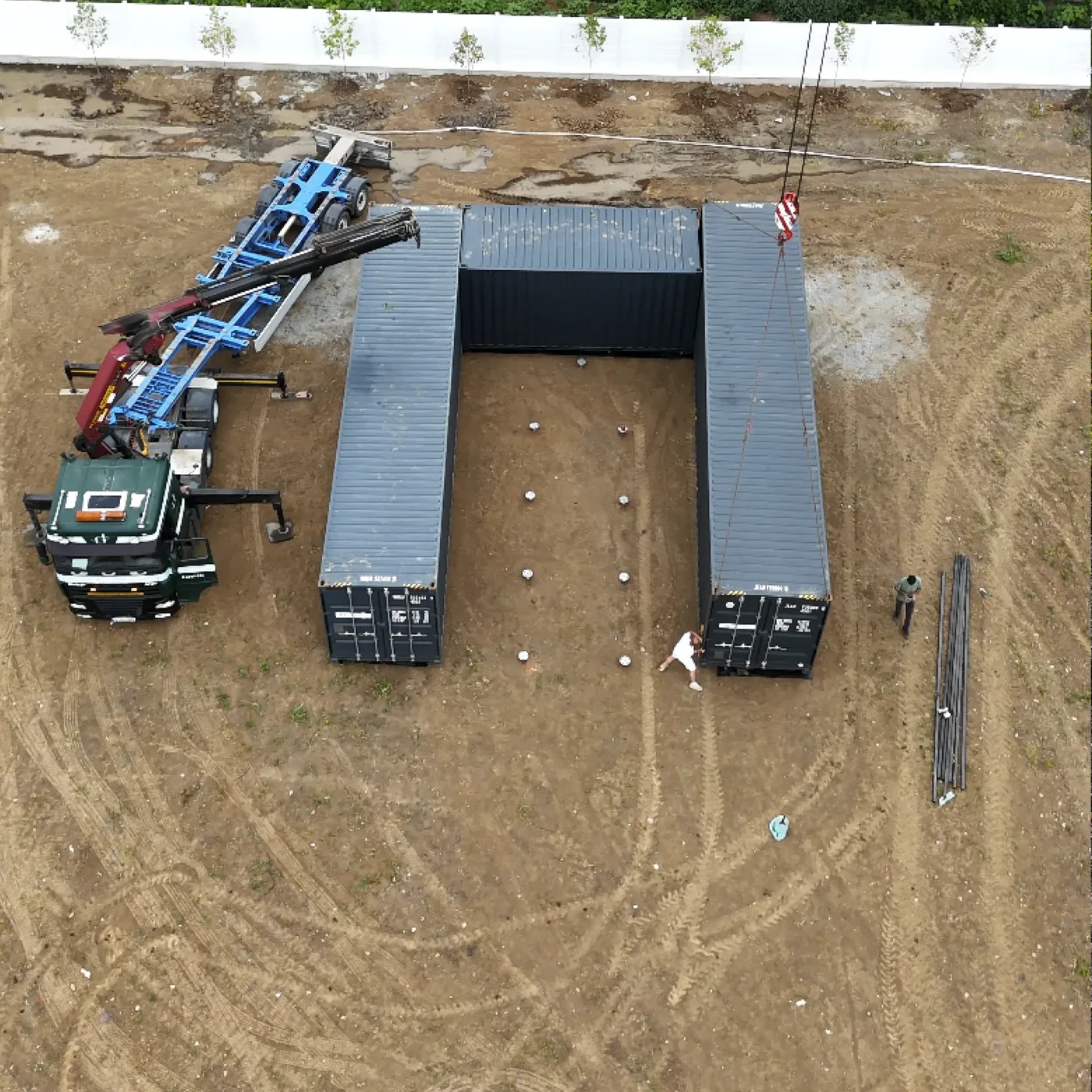
Three containers and a terrace, Cernica
The assembly consisted of three shipping containers and a shared terrace. The example shows why the formula “3 containers × 4 corners = 12 screws” does not necessarily describe the real foundation. The shared lines between modules, the terrace, the beams, the levelling and the way the whole assembly transfers its load into the foundation must be analysed.
How many screws are needed for a modular house?
For a modular house, the number of points is linked first of all to the modulation of the floor structure and the position of the load-bearing walls. The main beams, the joints between modules, the load-bearing exterior and interior walls, large openings, glazed façades, the roof, terraces and areas with concentrated loads all matter.
As a preliminary benchmark, a single-storey modular house of 50–60 m² can start, in certain configurations, from about 15–24 points. For about 80–100 m², 20–36 points may frequently appear. For larger areas, ground-plus-one storeys, large glazing, heavy roofs or large spans, the configuration must be analysed separately.
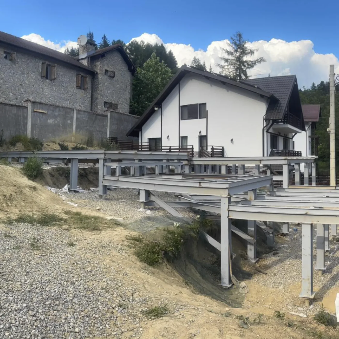
SIP house in Bușteni
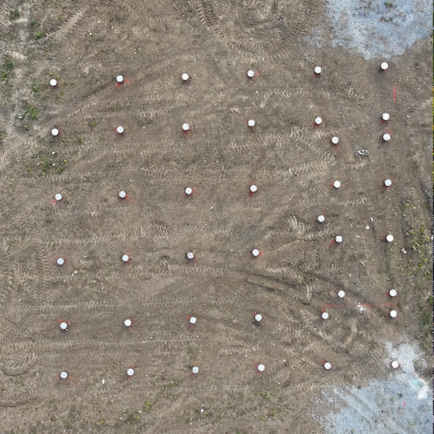
For the ground-floor-plus-attic house built in the SIP system and supported by an HEA platform, the foundation had to be analysed together with the steel platform, the level differences and the conditions of the mountain site. It does not mean that every SIP or ground-floor-plus-attic house needs 52 points.
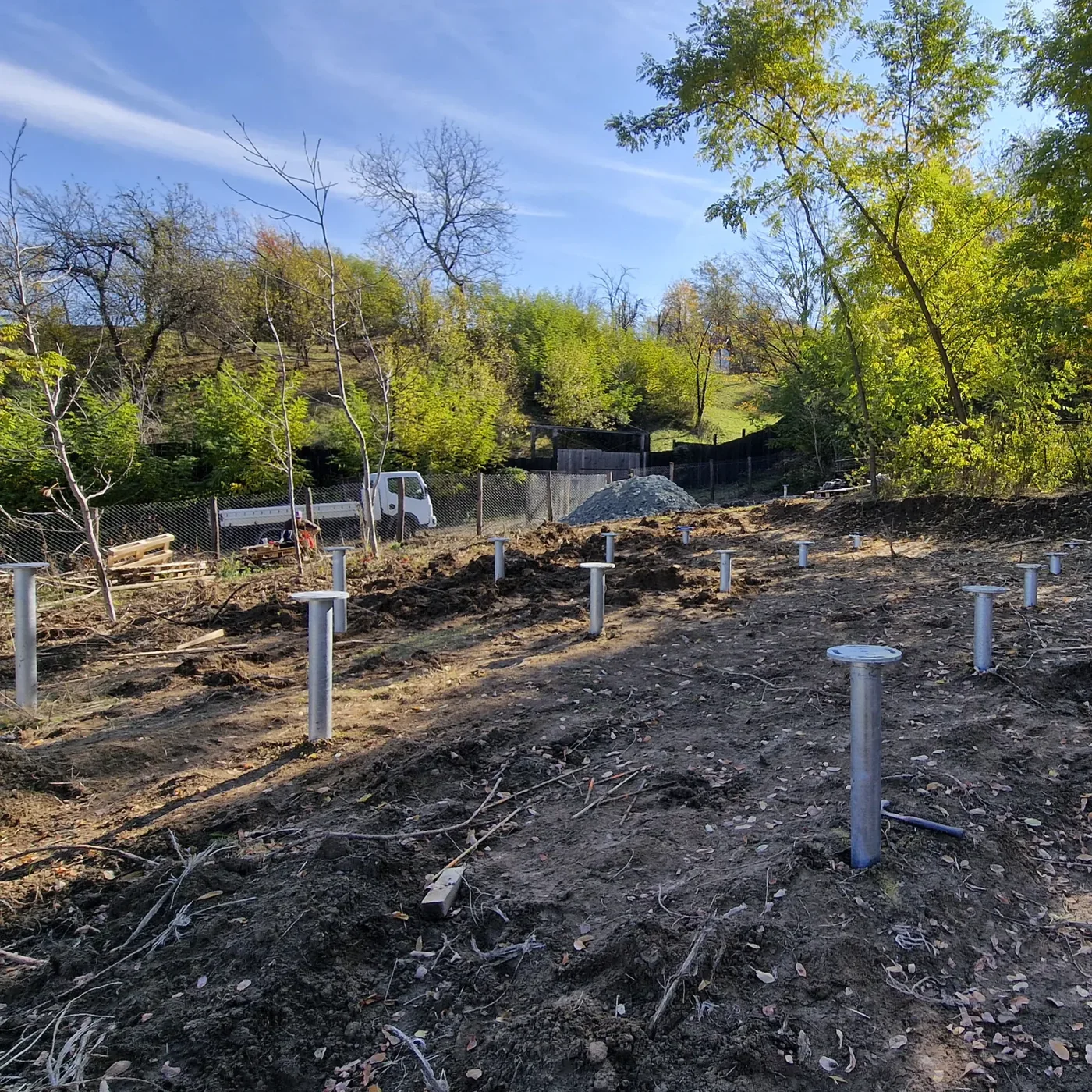
Three modular timber buildings in Provița de Jos
The site and the ground conditions influenced the chosen configuration. The 92 points are not a “recipe” for three houses. The value becomes relevant only together with the plans, the structures and the site of that project.
How many screws are needed for a terrace?
On terraces, the number of points is strongly influenced by the beams and the comfort of the floor. A terrace can be strong enough and still have a floor that vibrates or feels springy when the supports are too far apart.
For a terrace of about 20–30 m², indicatively 9–16 points may appear. For a 4.5 × 5.5 m terrace, a 3 × 3 grid may be too sparse for certain timber sections. A 4 × 3 grid can be a more suitable starting point, and in other configurations 15–16 supports may appear.
The number can increase if the terrace includes a hot tub, an outdoor kitchen, heavy planters, steps, several levels, reduced-section beams, a great height above the ground, or finishes sensitive to deformation.
How many screws are needed for a pergola, gazebo or carport?
For a simple pergola, the first thought is often: number of posts = number of screws. Sometimes this can be the solution. For example, a simple pergola with four posts can have four points if the structure, the bracing, the foundation and the site conditions allow it.
But a light roof does not automatically mean small loads. Wind can produce uplift and significant moments at the base of the posts.
| Application | Indicative |
|---|---|
| Pergola 3 × 3 m | 4 points can be considered |
| Pergola 3 × 6 m, six posts | 6 points can be considered |
| Gazebo 6 × 6 m | approx. 8–12 points |
| Double carport | approx. 6–10 points |
What is the distance between foundation screws?
There is no universal distance of 1.5 m, 2 m or 3 m that is correct for any building. The spacing is controlled simultaneously by two things: the structure above and the foundation in the ground.
The beam between two points must be able to span the distance without excessive deformation. At the same time, the screws must not be positioned without taking into account how each one mobilises the surrounding ground and any group effects.
Does a bigger screw mean we can put fewer points?
Sometimes yes, but not automatically. If we go from an M76 to an M89 and the screw can take a higher load, that does not mean we can simply remove every second point.
The beam or the chassis must be able to span the new distance between supports, the connections must be suitable, the reactions at the remaining points increase, and the displacements must be checked. Two M76 screws are not automatically equivalent to one M89.
If we put more screws, does the foundation become safer?
Not necessarily. More points do not automatically mean a better foundation. Each additional screw must be set out, installed, brought to level, connected and checked.
A grid that is too dense means more products, more connections, more installation time and a greater risk of differences between points. In addition, screws that are close together can influence the same volume of ground.
The optimal foundation is not the one with the fewest screws, but not the one with the most either. It is the one in which each point has a clear role and transmits the load correctly to the ground.
How does the ground influence the number of screws?
Very much. A good, relatively uniform layer can allow a simpler configuration. A site with uncontrolled fill, very soft ground, water, coarse gravel, boulders or shallow rock may require a completely different approach.
Sometimes the solution means longer screws. Other times a modular system. Sometimes testing is necessary. And in certain situations foundation screws may not be the right solution.
If a screw has a lower capacity than assumed, the answer is not automatically “let's put two more next to it”. A change of length, model, grid or even the foundation solution may be needed.
What loads must be taken into account?
The weight of the building is only one of them.
The weight of the building, people, furniture, snow and equipment push the foundation downwards.
Wind can try to lift certain areas of the building, especially the corners and edges of lightweight structures.
Wind, earthquakes or other actions can produce horizontal loads.
Tall posts, masts, panels or frames can transmit significant moments to the foundation.
What matters is how much each point moves and whether the points move differently.
Several screws close together do not automatically mean we can multiply a screw's capacity by their number.
Indicative example: a modular house of about 80 m²
Let's take a simplified example: a single-storey house of about 8 × 10 m. Suppose the structure allows three longitudinal support lines, one on each edge and one in the centre.
3 lines × 8 axes
That does not mean an 80 m² house needs 24 screws. It means 24 can be a starting grid for the hypothetical structure described. After calculation, certain points may have larger reactions, the beams may require another spacing, the ground may call for another product, and wind may govern the edge points.
How do we set a preliminary MARTETIC configuration?
Plan, dimensions, number of storeys and building system.
Corners, beams, longitudinal members, load-bearing walls, joints and areas with concentrated loads.
We determine the number of lines and axes that can work with the structure.
Depending on the application, the MARTETIC G, M, V ranges or Custom configurations can be considered.
Access, slope, utilities, obstacles and logistics.
The designer, geotechnical documentation and testing, where applicable.
Products, installation, transport, connections and documentation.
Can the number of screws change during installation?
It can happen that a point provided for in the design cannot be installed exactly in the desired position or to the desired depth. Buried concrete, a boulder, an underground network, an old foundation or lack of machine access may appear.
But the solution is not to move the screw “a bit further over” and carry on. If the position of a support must change, it must be checked how the load will be transmitted to the new position. It may be necessary to move the point, change the product, introduce a distribution beam or modify the solution.
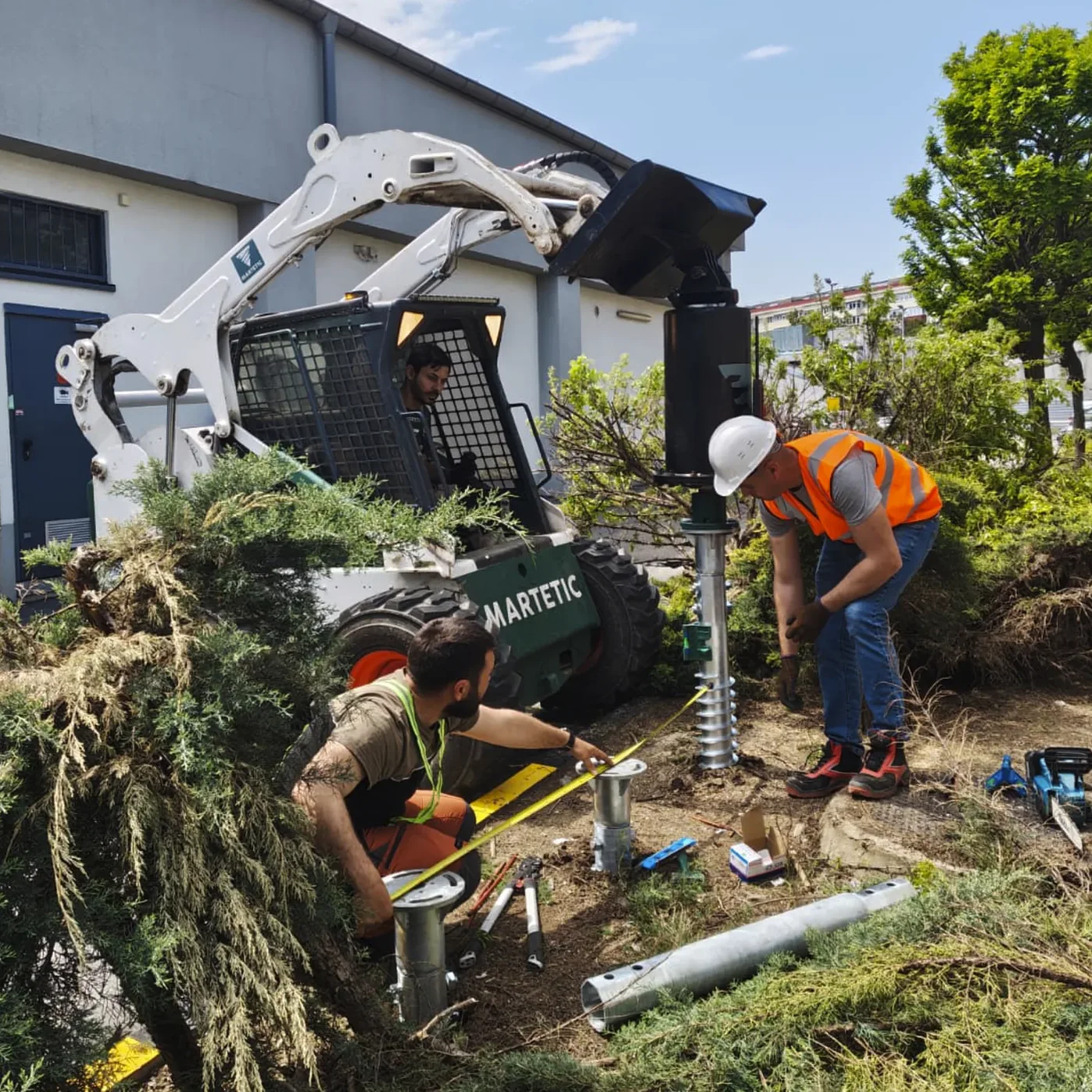
What do we check during installation?
A foundation is not finished just because all the screws have gone into the ground.
- the position relative to the axes;
- the top level;
- the verticality;
- the integrity of the product;
- the flanges and the connections;
- the parameters available from the installation;
- the documentation of the work;
- testing, if provided for.
These checks are especially important when the prefabricated building must arrive later and fit exactly over the installed points.
Frequently asked questions
What do you need to send us to estimate the number of points?
For a first analysis, the following are useful: the building plan or the chassis plan, the dimensions, the number of storeys, the building system, the position of the beams and load-bearing walls if known, the weight or reactions of the structure if available, the locality, photographs of the site, the level differences, the geotechnical study if it exists, and information about access and utilities.
With this information we can discuss a preliminary support grid, the products that can enter the analysis and the installation conditions.
The right number is a result, not an assumption
For some buildings the answer may be 4 or 6. For others it may be 12, 24, 40, 50 or more. The figure alone says very little.
What matters is where each point is, what structural element it supports, what load it receives and how it transmits that load into the ground.
A well-conceived foundation does not start with choosing the biggest screw, nor with copying a grid seen on the internet. It starts with the building. Then we determine the supports, analyse the ground, choose the right products and prepare the installation.
Have a project and want to find out how many points you might need?
Send the plan or sketch of the building, the dimensions, the locality, the building system and the information available about the ground.
Send the project for analysis