
Martetic foundation screws:
the G, M, V and Custom series
Standard products, modular systems and configurations adapted for modular structures, platforms, fences, signage and technical projects.
More than a product
We analyse the project, choose the right solution, install and check the foundation in the ground. The Martetic range includes standard foundation screws, modular systems and configurations made for special projects.
There is no single screw suited to every project. Diameter, thickness, thread geometry, length, flange, ground and connection method must be considered together.
Products only
We supply the foundation screws and the parts needed for installation by your own team.
Products and installation
We select the configuration, handle the logistics and carry out mechanised installation.
Testing and custom parts
We can include the contracted tests and parts adapted to the structure or the connection.
See the product in 3D, from any angle
Interactive 3D model of a Martetic modular pile. Rotate, zoom and explore the real geometry of the product before choosing the configuration right for your project.
Foundation screw, steel pile, screw pile or eco-pile?
In Romania, this category of products is searched for under several names. “Foundation screw” is the commercial name we use for the product. “Screw foundation” describes the complete support system, while “screw-in steel pile” and “screw pile” are frequently used for similar solutions.
The term “eco-pile” is used commercially on the market for certain products in this category. On the Martetic website we mainly use the names “foundation screws” and “steel screw foundations”, followed by the exact family and configuration of the product.
The commercial name does not replace technical selection according to the project, ground and loads.

Four directions. One selection principle.
The choice starts with what you are building and continues with the ground, depth, loads and the connection to the structure.
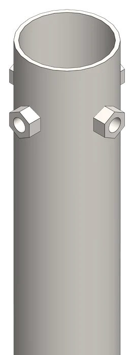
G Series
Direct fixing for vertical elements
For fences, gates, posts, panels, signage and small structures.
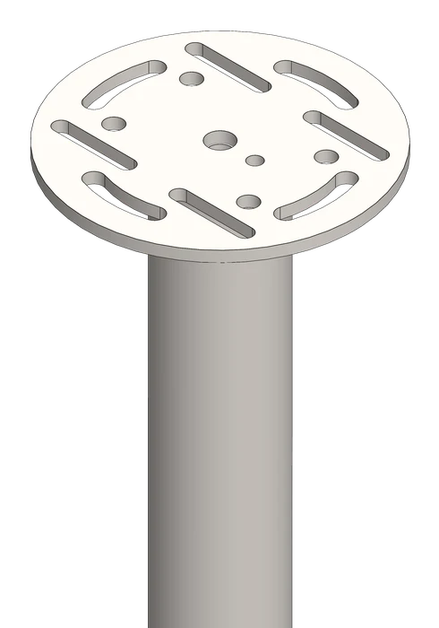
M Series
Fixed flange for platforms and structures
For terraces, containers, modular houses and LSF, Timber Frame or steel frames.
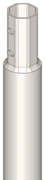
V Systems
Separate tip, extensions and flange
Modular systems V76, V89 and V114, configurable for additional depth.
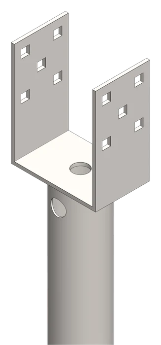
Custom Configurations
Parts adapted to the project
Flanges, holes, heads, brackets, gussets and stiffeners made to the connection requirements.
G Series
Direct fixing for posts and vertical elements
The G Series is intended for fences, gates, signage, posts for light lighting and small structures. Height, wind-exposed area, stiffness and ground must be analysed for each project.

Where it fits
- Fences and gates
- Posts for light lighting
- Panels and signage
- Vertical elements and small structures
Fixing
- G4 × M12 for connecting posts or connecting parts with a rectangular cross-section.
- G3 × M16 for connecting elements with a circular cross-section.
| Standard model | Fixing | Indicative use |
|---|---|---|
| G Ø76 × 2.7 × 800 mm | G4 × M12 / G3 × M16 | Fences and posts for light-duty applications |
| G Ø76 × 2.7 × 1,200 mm | G4 × M12 / G3 × M16 | Taller posts or deeper bearing layer |
| G Ø89 × 2.7 × 1,200 mm | G4 × M12 / G3 × M16 | Vertical elements with higher loads |
Watch out for wind
A tall post or a large-area panel is not selected only by the screw diameter. Ground, height, lever arm, stiffness and the spacing between supports matter.
M Series
Fixed flange for platforms and structures
The M Series uses a welded round flange, prepared for connecting base plates and timber or steel frames.

Typical applications
- Terraces and platforms
- Modular houses and containers
- LSF and Timber Frame structures
- HEA/IPE frames and professional projects
- Masts and equipment, subject to verification
Connecting the structure
The position of the holes, the base plate size, the type and diameter of the fasteners, and the rigidity of the connection are determined by the structure, the loads and the details of each project.
| Standard model | Flange and thread | Indicative use |
|---|---|---|
| M Ø76 × 3.6 × 1,200 mm | Ø200 × 8 mm, M16, thread 15 × 3 mm | Small platforms, terraces and lightweight structures |
| M Ø76 × 3.6 × 1,500 mm | Ø200 × 8 mm, M16, thread 15 × 3 mm | Timber frames and lightweight modular buildings |
| M Ø76 × 3.6 × 2,000 mm | Ø200 × 8 mm, M16, thread 15 × 3 mm | Additional depth, depending on the ground |
| M Ø89 × 3.6 × 1,500 mm | Ø220 × 12 mm, M24, thread 20 × 3 mm | Modular houses, LSF and professional structures |
| M Ø89 × 3.6 × 2,000 mm | Ø220 × 12 mm, M24, thread 20 × 3 mm | High loads and depths, per project |
| M Ø89 × 3.6 × 2,500 mm | Ø220 × 12 mm, M24, thread 20 × 3 mm | Higher loads and greater depths, per project |
The table shows standard models. Other diameters, thicknesses, threads, lengths and flanges can be produced according to the project's requirements.
Diameters, thicknesses and thread geometries for different projects
For special projects, the M Series can be adapted to the structure’s requirements and the installation conditions.
| Parameter | Available options |
|---|---|
| Body diameter | Ø76 / Ø89 / Ø114 / Ø140 mm |
| Wall thickness | 3.6 / 4.5 / 5.6 mm |
| Thread geometry | 12 × 2 / 15 × 3 / 20 × 3 / 20 × 4 mm |
| Flange stiffening | With gussets / without gussets |
| Flange and holes | Standard model or per drawing |
| Length | Standard or set for the project |
Gussets under the flange
They locally stiffen the connection between the screw body and the flange. The number, thickness and geometry are determined for the required configuration.
Thread geometry
It influences how the screw interacts with the ground and is chosen according to the soil type and the project.
Not all combinations are permanently in stock. Standard variants, made-to-order products and custom configurations are confirmed before the offer.
V76, V89 and V114 modular systems
Three diameters. The same modular logic.
The tip works in the ground, the extensions take the system to the required depth, and the flange makes the connection to the structure.

Tip
Enters the chosen soil layer.
Extension
Increases the depth of the system.
Flange
Connects the foundation to the structure.
V76
Ø76 mmFor platforms and lightweight structures
- Tip
- 1,200 / 1,500 / 2,000 mm
- Extensions
- 500 / 1,000 / 1,500 / 2,000 mm
- Flange
- Round flange Ø200 × 8 mm
Platforms, lightweight structures and projects where the depth must be adjusted on site.
V89
Ø89 mmFor larger structures and depths
- Tip
- 1,500 mm
- Extensions
- 1,000 / 1,500 mm
- Flange
- Round flange Ø220 × 12 mm
Modular houses, containers, platforms and steel frames, after technical selection.
V114
Ø114 mmFor higher loads and larger projects
- Tip
- 1,500 mm
- Extensions
- 1,000 / 1,500 mm
- Flange
- Round flange Ø220 × 12 mm
Heavily loaded structures, tall elements and industrial applications. Gussets available in certain configurations.
The right choice is not made by diameter alone. The system is configured according to the project and the real conditions on site.
When the project doesn’t fit a standard product
We can coordinate adapted parts and configurations, after analysing the drawings, quantity and documentation required.
Flanges and holes
Diameters, thicknesses, holes and cut-outs adapted to the base plate.
Gussets and stiffeners
Local stiffening for the flange and the connection area.
Heads and brackets
Fixings for timber, steel, posts, masts and equipment.
What you need to send
The connection drawing, dimensions, the structure’s material, known loads, quantity and deadline.
What we confirm
Feasibility, dimensions, minimum quantity, deadline, available documentation and cost.
Examples
Masts, signage, lighting, machinery, equipment, atypical frames and industrial structures.
Rule
We do not declare a custom part compatible or load-bearing before the project has been checked. A commercial sketch does not replace the technical drawing or the structural design.
From project to the right family
The table is a starting point. The final selection is confirmed after ground, structure, loads and installation conditions.
| What you are building | Family under consideration | What must be checked |
|---|---|---|
| Fence, gate or post | G / M | Wind, height, spacing, ground |
| Terrace or pergola | M76 / V76 | Beams, levels, ground, drainage |
| Tiny house or cabin | M76 / M89 / V76 / V89 | Weight, support points, geotechnical study |
| Container or modular office | M89 / V89 | Bearing points, flatness, access |
| Modular house, LSF or Timber Frame | M89 / V89 / V114 | Structural design, ground, testing |
| Signage and panels | G / M / Custom | Wind-exposed area, moment, fixing |
| Mast or lighting | M / V114 / Custom | Wind, vibration, uplift, lateral load |
| Solar and equipment | G / M / V / Custom | Geometry, groups, corrosion, maintenance |
Don’t choose by area alone. Two buildings with the same footprint can have very different weights, stiffness and loads. The number and position of the screws are determined by the structure, not just by square metres.
Capacity is determined for the exact product and site
The capacity of a screw foundation depends on the product geometry, depth, ground, installation method, loads and group effects.
We do not use a general value valid for all sites. For preselection, we analyse the project and the available geotechnical information. For relevant works, recording of installation parameters and compression or uplift tests can be included.
The values used in design are determined through the technical documentation applicable to the product and the project.
PDF document · 503 KB
Table of approximate load capacities
Indicative values, useful for product preselection.
Problematic ground
Uncontrolled fill, topsoil, organic soil, soft clay or loose sand may require investigation, additional depth or a different solution.
Medium ground
Stiff clays and medium-dense sands must be confirmed through local information and installation parameters.
Good ground
Hard clays, dense sand or a dense sand-and-gravel mix can offer favourable conditions if the product reaches the right layer.
Very hard ground or ground with obstacles
Boulders, concrete, rock and coarse gravel may require pre-drilling or repositioning, or may prevent installation.
From ground to a foundation ready for the structure
We can take on installation only, or a broader flow with setting-out, logistics, site preparation and the connection with the structure.
01
We understand the project
Structure, dimensions, support points, ground and access.
02
We choose the variant
Family, diameter, length, flange and the services needed.
03
We prepare the works
Setting-out, utilities, access, materials and machinery.
04
We install mechanically
Screwing in and control of position, level and verticality.
05
We verify
Installation parameters and contracted tests.
06
We hand over
Acceptance report and the documents provided for in the offer.
Identified products, documents and checks as per the offer

Technical data sheet
Describes the product, its dimensions and declared use.

Declaration of Performance, DoP
Presents the performance declared by the manufacturer.

CE marking
Applies to products covered by the harmonised standard and under the conditions set out in the product documentation.

EN 1090 and EXC2
Documentation for structural steel components, within the applicable scope.

Hot-dip galvanising ISO 1461
The corrosion-protection standard for coated products.

EPD
Environmental declaration available for the covered products.

Traceability
The delivered product can be identified by its manufacturing code and batch.

Acceptance report and record
Confirms the works and checks actually contracted and carried out.
The documents provided are set out in the offer, depending on the product, configuration and the services contracted.
Tell us what you want to build
You don’t have to choose the diameter or length yourself. Send the structure, location, dimensions and the information available about the ground. We propose the product family and the steps needed for the quote.