BESS FOUNDATIONS · ENERGY & SITE INFRASTRUCTURE

Difficult ground. A simpler civil strategy.

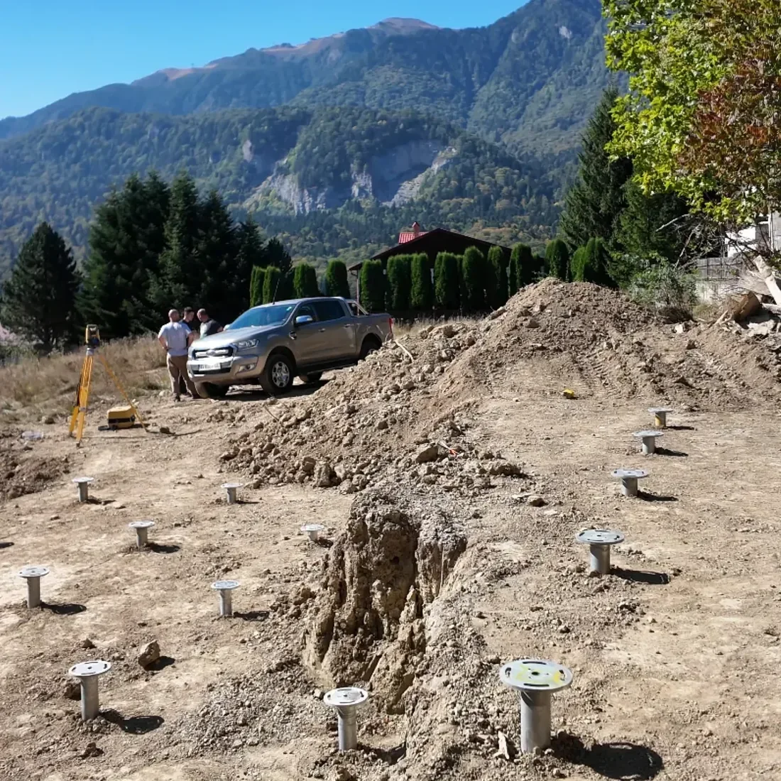
MARTETIC develops screw-foundation concepts for BESS equipment, auxiliary infrastructure and temporary site works — with particular value where weak upper soils, high groundwater or repetitive civil work make conventional foundations difficult to execute.

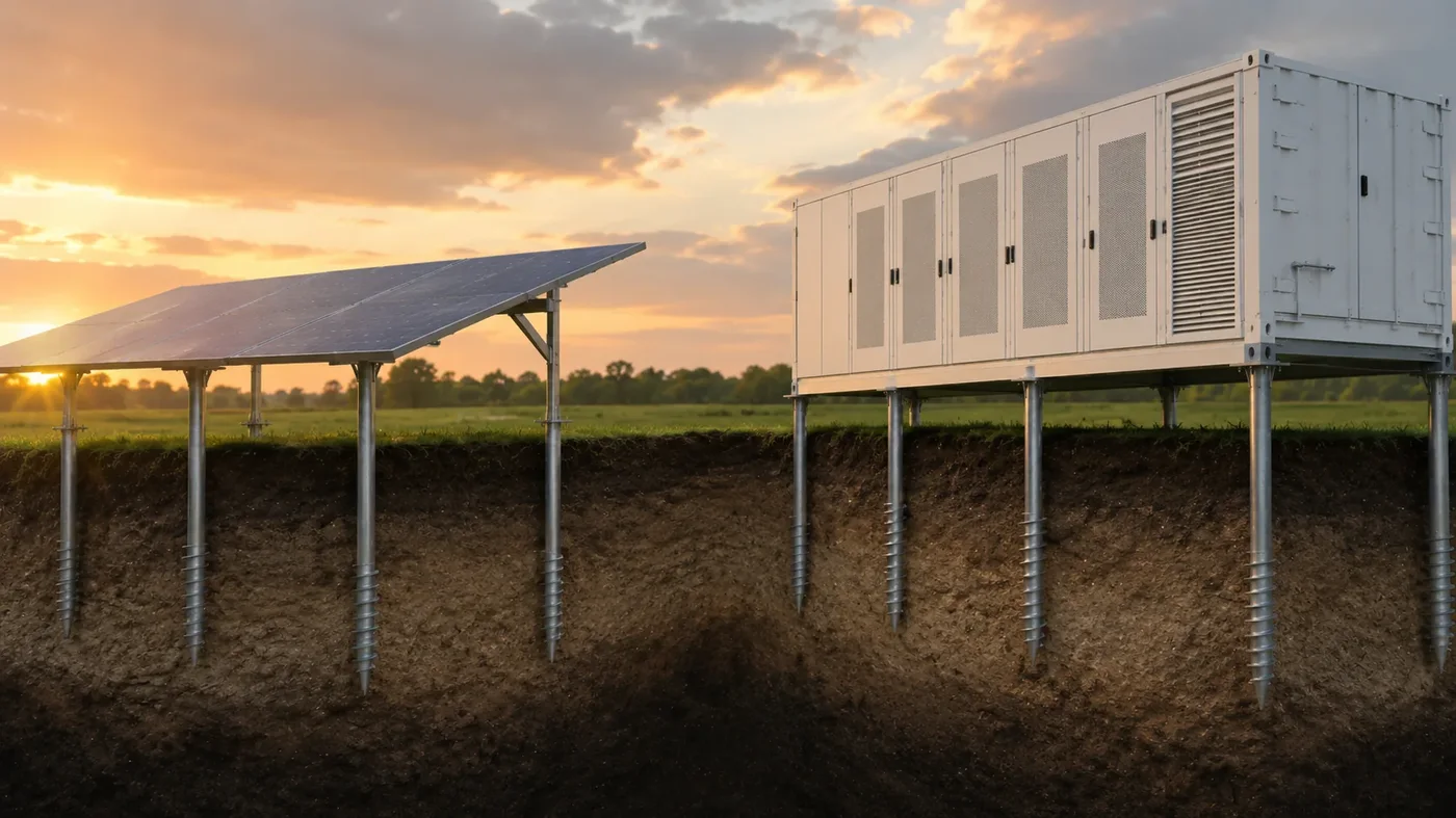
BESS and solar installation on screw foundations
PermanentBESS, PCS, control modules, technical supports
Balance of sitePV, lighting, CCTV, gates, fences, instrumentation
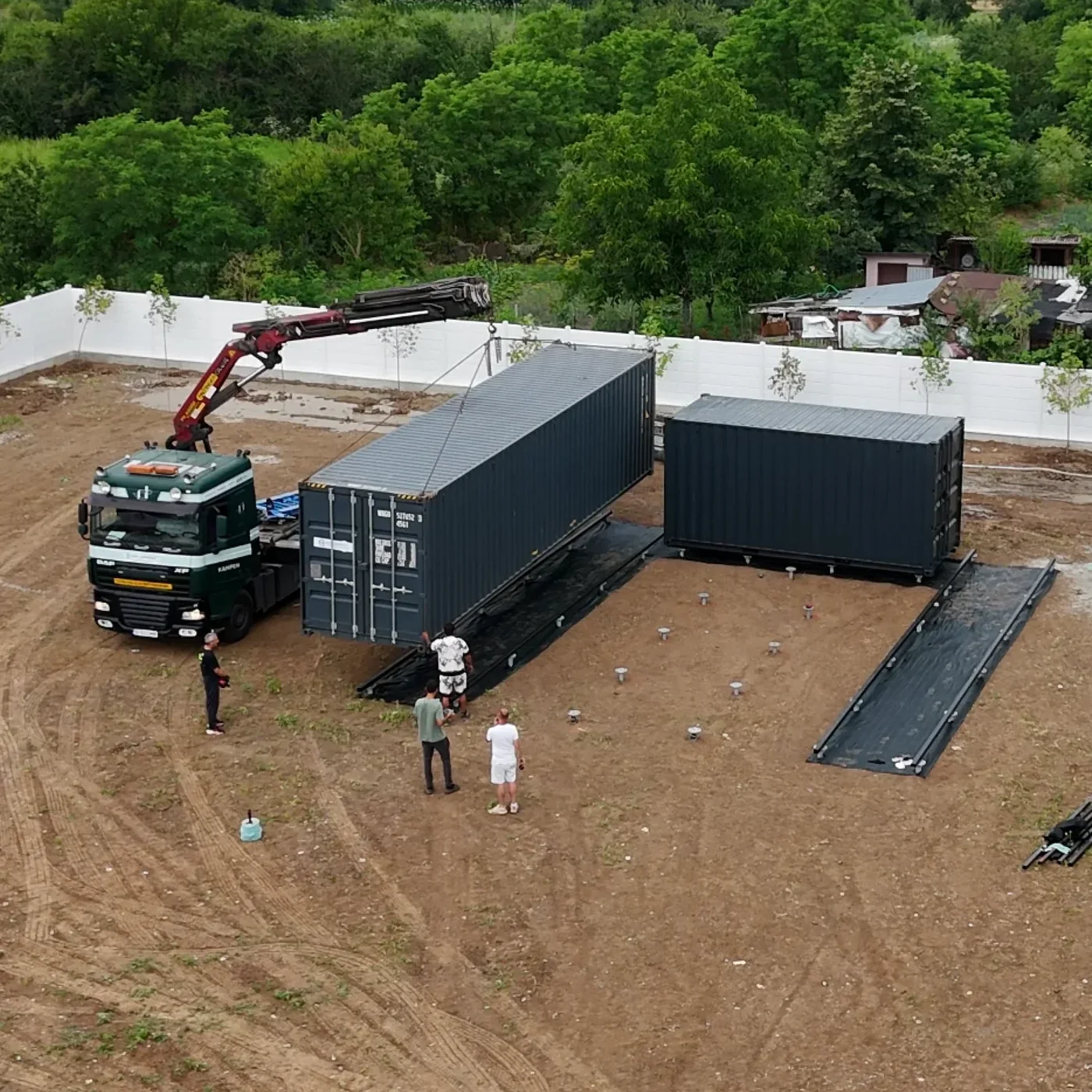
Temporary worksSite containers, offices and relocatable infrastructure
Our approach: We do not try to replace concrete everywhere. We use screw foundations where they create a better project outcome, and hybrid solutions where conventional foundations remain the rational choice.
01 / WHERE VALUE APPEARS

The opportunity is not the screw. It is the civil work you can simplify.

The strongest candidates are sites where the foundation package is becoming disproportionate to the equipment it supports — especially when the same detail repeats dozens of times.

↧

Weak upper soils

Where a competent layer exists deeper, a modular foundation may allow the weak upper zone to be crossed rather than used as the bearing layer.

≈

High groundwater

Potential to reduce selected open foundation excavations and wet civil operations, subject to project-specific groundwater and corrosion checks.

×N

Repetitive layouts

A repeatable support detail can turn a one-off foundation idea into an installation system across a BESS block or whole site.

↻

Temporary infrastructure

Site offices, lighting, fences, gates and selected technical structures can be designed for demounting or relocation where the project requires it.

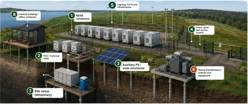
02 / INTERACTIVE BESS SITE

One site. Several foundation scopes.

Select a numbered area to see where MARTETIC can be considered. Not every element needs the same foundation strategy.

Interactive BESS site map

    Click the numbered zones in the image. The foundation concept is confirmed only after the actual project inputs are reviewed.
    03 / CHOOSE YOUR PERSPECTIVE

    The same foundation decision has different consequences for each project team.

    BEST STARTING INPUT

    04 / DIFFICULT GROUND

    Do not ask the weak layer to carry the BESS.

    For difficult sites, the real engineering question is whether the weak upper zone can be crossed and a suitable deeper layer can be engaged at a practical depth.

    S0

    Problematic soil = no catalog capacity

    Uncontrolled fill, topsoil, soft clay, organic soil and loose / saturated sand are treated as problematic. They require additional investigation, extra depth, local improvement or project-specific verification.

    S1 / S2

    Target a confirmed bearing layer

    Preliminary capacity ranges only become relevant when the soil scenario and working depth are supported by the actual geotechnical information.

    HYBRID

    Use the rational solution by equipment type

    BESS and auxiliary structures may use screw foundations while heavy transformers, crane areas or OEM-mandated details remain conventional.

    05 / MODULAR FOUNDATION SYSTEM

    Configure depth to the project — not the project to one stock length.

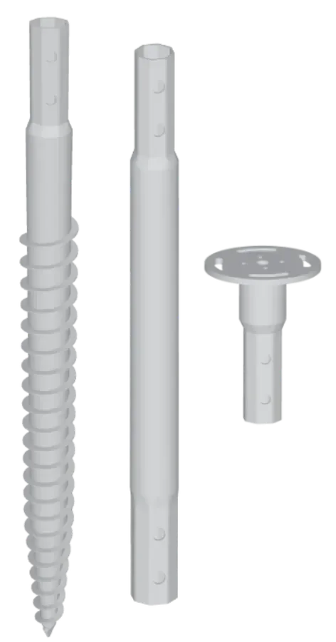
    MARTETIC modular V ground screw system
    V89 / V114

    Modular families for deeper / higher-load applications

    The concept uses a screw tip, one or more extensions and a separate structural flange. Exact product configuration and documentation are confirmed for the contracted project.

    INTERFACE

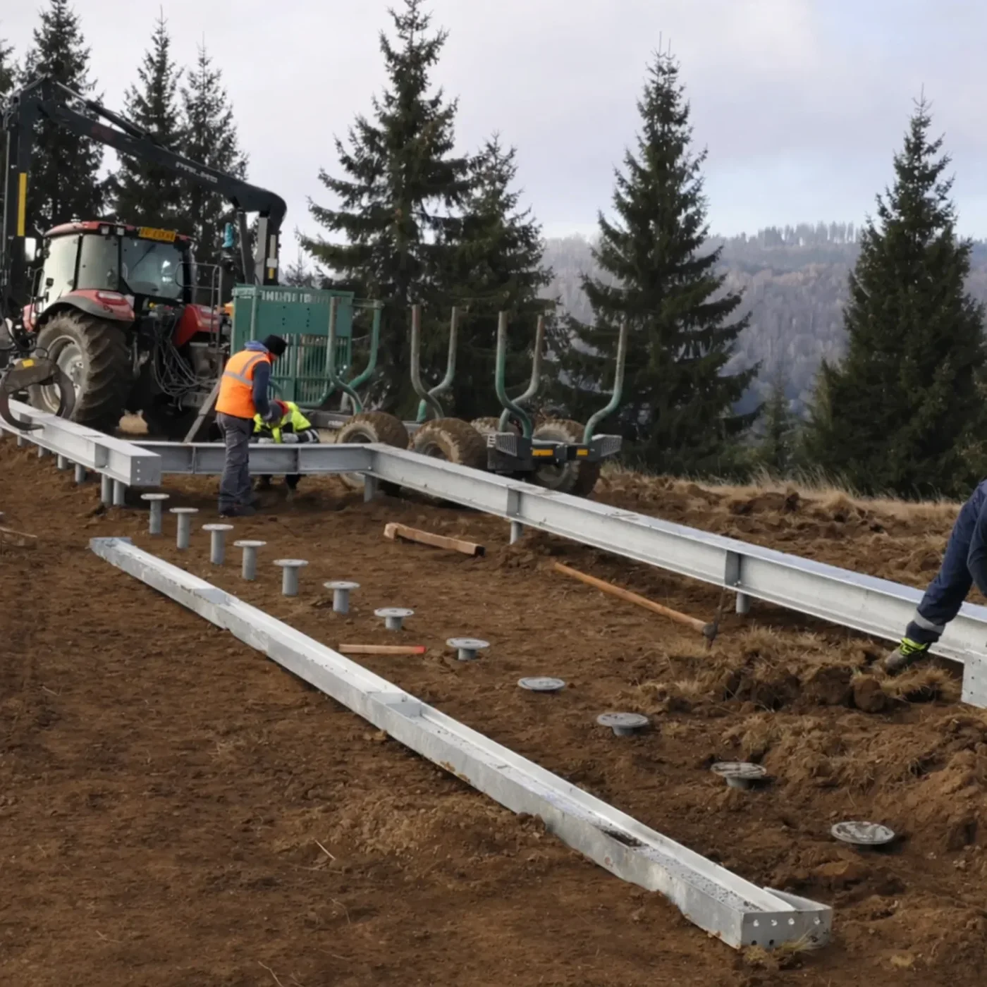
    Direct support or steel distribution frame

    The structural interface follows the equipment support geometry. A steel IPE/HEA frame is introduced only where it is useful for load distribution, level control or OEM interface requirements.

    INSTALLATION

    Position, level and depth are controlled as project parameters

    The foundation system is delivered as an installation scope, not simply as loose components. Access, tolerances and available installation records are defined before execution.

    VERIFICATION

    Project-specific engineering remains essential

    Settlement, uplift, lateral loads, moments, group effects and corrosion are checked for the actual project. If verification testing is required by the designer or beneficiary, it is treated as a separate specialist project scope.

    V89 · 3.0 m TOTAL DEPTH

    Published preselection range

    28–45 kNS1 compression≈ 2.8–4.5 tf
    40–65 kNS2 compression≈ 4.0–6.5 tf
    18–30 kNS1 uplift≈ 1.8–3.0 tf
    26–44 kNS2 uplift≈ 2.6–4.4 tf
    V114 · 3.0 m TOTAL DEPTH

    Heavy-duty preselection range

    40–65 kNS1 compression≈ 4.0–6.5 tf
    60–90 kNS2 compression≈ 6.0–9.0 tf
    25–45 kNS1 uplift≈ 2.5–4.5 tf
    40–60 kNS2 uplift≈ 4.0–6.0 tf
    Technical note: these are MARTETIC 2026 preliminary single-screw axial ranges at 3.0 m total depth. They are not characteristic values, allowable loads, design values or guaranteed capacities. 10 kN ≈ 1 tonne-force is shown only to communicate order of magnitude.
    06 / WHAT CAN BE INCLUDED

    One coordinated foundation package — or only the part your EPC needs.

    01

    Preliminary foundation concept

    Screen the project before detailed civil engineering is committed.

    • Site / geotechnical review
    • Indicative family and depth strategy
    • GO / HYBRID / NO-GO
    02

    Products & installation

    A controlled supply-and-installation scope for the selected foundation points.

    • Screws, extensions and flanges
    • Mechanised installation
    • Position / level / depth records according to scope
    03

    Steel interface & site infrastructure

    Where required, the foundation package can extend beyond the screw itself.

    • IPE / HEA distribution frames
    • Temporary site infrastructure
    • Auxiliary and BOS support points
    07 / DELIVERY LOGIC

    A foundation should arrive as a sequence, not as a coordination problem.

    01

    Project inputs

    GA, reactions, geotechnical profile and site constraints.

    02

    Preliminary decision

    GO / HYBRID / NO-GO and an indicative foundation strategy.

    03

    Set-out & interface

    Support points coordinated with equipment, steel and site services.

    04

    Installation

    Mechanised installation, depth / position control and structural interface.

    05

    Handover

    Scope-specific records and project documentation.

    08 / WHY MARTETIC

    Built for site execution — not only product supply.

    For a BESS project, the useful question is not only whether a ground screw exists. It is whether the complete foundation interface can be installed, controlled, documented and integrated into a repeatable construction sequence.

    Foundation concept → products → mechanised installation → controlled handover

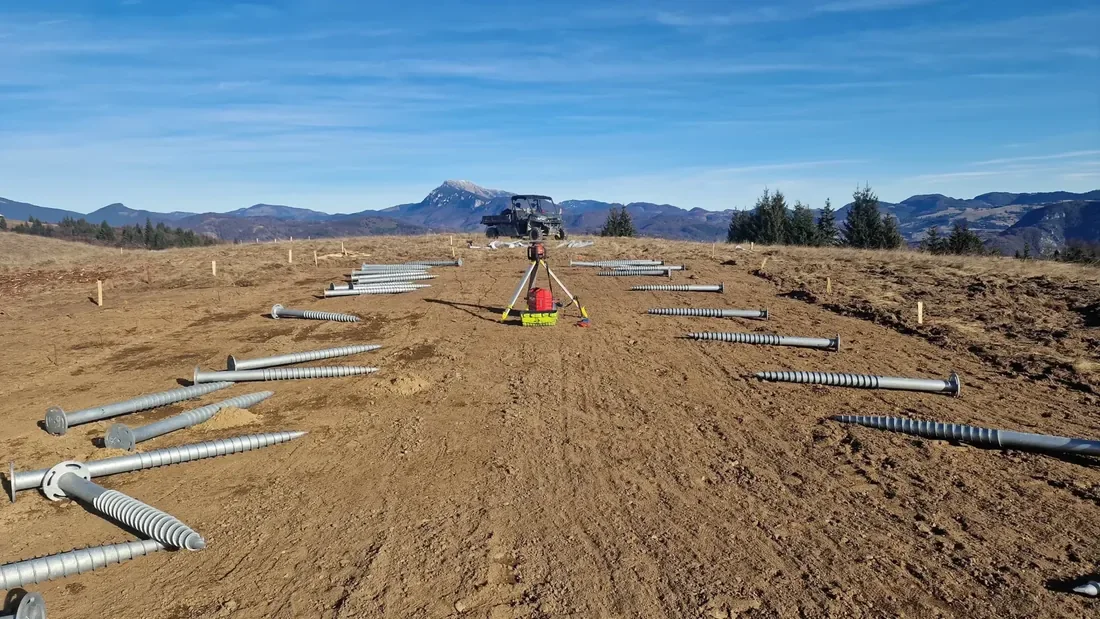
    MARTETIC combines ground-screw products with installation equipment, site set-out and levelling capability, local site preparation, transport coordination and structural connection solutions. The exact project scope is defined before mobilisation.

    ⚙
    MECHANISED

    Installation equipment matched to the project

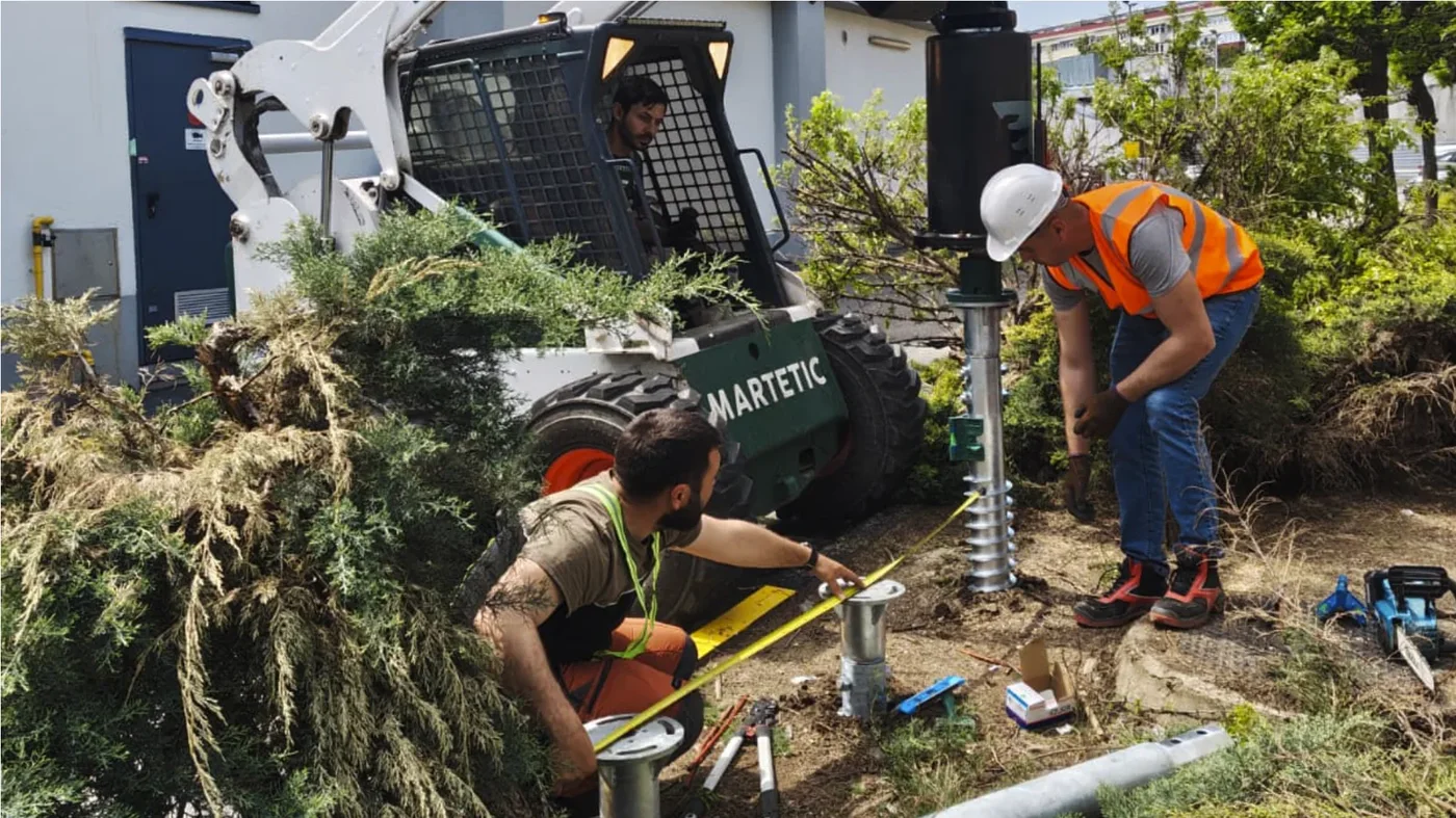
    Installation equipment and reducers are selected for the screw diameter, length, required installation torque, ground conditions and site access.

    ×N
    SCALABLE

    Designed for repetitive, high-volume layouts

    Mechanised installation makes repetitive BESS grids commercially interesting. Daily productivity is established for the actual product configuration, soil, spacing, access and site logistics rather than promised as one universal number.

    ◎
    CONTROLLED

    Position, level, verticality and depth

    The installation process checks the support axis, plan position, final level and verticality. After installation, the model, position, depth, level and available installation parameters can be recorded according to the contracted scope.

    ↕
    TESTABLE

    Project-specific load testing can be included

    Where required by the designer, EPC or beneficiary, compression and uplift testing — and, where relevant, lateral testing — can form a separate specialist project scope. The test measures load–displacement response; the measured result does not automatically become the design load.

    ▤
    DOCUMENTED

    Product, lot, installation and test records

    Depending on the exact selected product and contracted package, project documentation can include technical identification, DoP / CE information where applicable, traceability, fabrication / galvanizing documentation, installation records and a testing report when testing is contracted.

    ▱
    SITE READY

    Set-out, levelling, handling and steel connections

    Laser set-out and levelling, Bobcat-supported local site work, product / equipment transport, unloading coordination and custom steel connection pieces can be integrated where they are part of the agreed project scope.

    A BESS project should not depend on one impressive installation-speed claim.

    For a real tender, MARTETIC can define an indicative production rate after the screw type, depth, ground, spacing, access, number of repeated points and logistics are known. That gives the EPC a usable programme assumption instead of a generic marketing number.

    What the client can ask us to define

    Indicative daily installation rate · required equipment · access envelope · installation sequence · control / records · steel interface · documentation package · optional testing scope.
    09 / SCOPE CLARITY

    Define the interfaces before they become site problems.

    InterfaceTypical MARTETIC contributionProject team input
    GroundFoundation family / depth concept and installation scopeGeotechnical documentation, groundwater and site constraints
    BESS equipmentFoundation layout coordinated to permitted support geometryGA, reactions, anchoring and tolerance requirements
    Steel interfaceFlange / frame concept where included in scopeStructural design basis and OEM restrictions
    ConstructionInstallation methodology, equipment and agreed recordsAccess, sequencing, work areas and HSE requirements
    VerificationProduct and installation documentation within contracted scopeProject-specific design acceptance; specialist testing if required
    10 / FIT & LIMITS

    A credible NO-GO is part of a credible foundation system.

    STRONG CANDIDATE SIGNALS

    Worth a preliminary review

    • Weak upper soil but a better layer exists at practical depth
    • Groundwater complicates conventional foundation excavation
    • Many repetitive BESS / auxiliary support points
    • Temporary infrastructure must later be relocated
    • Civil package or programme is already a project risk
    POSSIBLE NO-GO / HYBRID SIGNALS

    Do not force the solution

    • No suitable layer within practical installation depth
    • Rock, boulders or obstructions make installation impractical
    • OEM requires a non-negotiable conventional foundation
    • Flood, scour, liquefaction or erosion risks remain unresolved
    • Screw + steel package is not competitive after a site-specific comparison

    Is your site worth screening?

    0 / 6
    11 / ENGINEERING DISCIPLINE

    Three things we will not sell as slogans.

    SOFT SOIL

    Not “works in any soft soil”

    The value may be in crossing a weak upper layer to reach a suitable deeper stratum. If that stratum does not exist at a practical depth, the concept may not be suitable.

    CAPACITY

    Not “X tonnes per screw everywhere”

    Published figures are preliminary ranges with declared soil and depth assumptions. Final project values are not copied from a catalogue.

    CONCRETE

    Not “zero concrete at any cost”

    The goal is a better site-wide foundation strategy. A technically sound hybrid solution is preferable to forcing one technology onto every equipment type.

    12 / PRELIMINARY PROJECT REVIEW

    Send one representative BESS unit and the geotechnical report.

    We can determine whether the site deserves a screw-foundation concept, a hybrid comparison or a conventional solution before significant engineering effort is spent in the wrong direction.

    MARTETIC · NZEB GROUP SRL

    +40 720 452 788

    [email protected]

    martetic.com


    Useful files for a first review:

    • General arrangement / support drawing

    • Equipment mass and support reactions

    • Geotechnical report and groundwater information

    • Site layout, access and conventional concept if available

    Technical basis and limitations
    • Preselection ranges shown in this presentation are taken from the MARTETIC 2026 approximate load-bearing capacity catalogue and are intended only for preliminary technical discussion.
    • Final foundation design depends on the exact ground, structure, product configuration, installation parameters and applicable project requirements.
    • MARTETIC technical documentation describes mechanised installation, checking of support position / level / verticality, recording of available installation parameters, and project-specific compression / uplift / lateral testing when required and contracted.
    • Reference framework includes project-applicable geotechnical design requirements such as NP 123-2022 and Eurocode 7; exact standards and documentation are confirmed for each project.